| |
|

|
|
|
|
|
|
|
|
|
|
|
|
|
|
|
|
|
|
|
| |
Wall
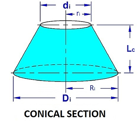
Thickness Calculation of Conical Section Under Internal Pressure
|
| |
| |
ASME
Section VIII Div 1 paragraph UG-32
Formed Heads, and Sections, Pressure On Concave Side
|
| |
UG-32(f)
Conical Heads and Sections (Without Transition Knuckle)
|
|
|
| |
|
|
| |
|
(Enter values in yellow cells for calculations)
|
| |
DATA INPUT
|
| |
|
|
|
|
|
|
|
|
|
|
|
|
|
|
|
|
|
|
|
|
| |
|
Design Conditions
|
|
|
Material
|
|
|
|
| |
|
Design Pressure, Pd =
|
|
psig
|
Conical
Section Material Specification (1 to 7)
|
|
|
|
| |
|
|
|
|
|
|
|
|
|
|
|
|
|
|
|
|
|
|
|
|
| |
|
Design Temperature, Td =
|
|
°F
|
Allowable
Stress Conical Section, S =
|
|
psi
|
|
| |
|
|
|
|
|
|
|
|
|
|
|
|
|
|
|
|
|
|
|
|
| |
|
Welding Efficiency, E =
|
|
|
Dimensions
|
|
|
|
| |
|
See Table UW-12
|
|
|
Large End
Inside Diameter, Di =
|
|
in.
|
|
| |
|
Corrosion Allowance, CA =
|
|
in.
|
Small End
Inside Diameter, di =
|
|
in.
|
|
| |
|
|
|
|
|
|
|
|
|
|
|
|
|
|
|
|
|
|
|
|
| |
|
Undertolerance Allowance (8)(9)(10), U1 =
|
|
default value = 0
|
|
|
Nominal wall
thickness, tn =
|
|
in.
|
|
| |
|
|
|
|
Minimum
required thickness (Large End), tr =
|
|
in.
|
|
| |
|
|
|
|
|
|
|
|
|
|
|
|
|
|
|
|
|
|
|
|
| |
|
|
|
|
Length of
Conical Section, Lc =
|
|
in.
|
|
| |
|
|
|
|
|
|
|
|
|
|
|
|
|
|
|
|
|
|
|
|
| |
|
|
|
|
|
|
|
(Large End) If tr ≤ tn acceptable
|
|
|
|
| |
|
|
|
|
|
|
|
(Small End) If tr ≤ tn acceptable
|
|
|
|
| |
|
Notes:
|
|
|
|
|
|
|
|
|
|
|
|
|
|
|
|
|
|
|
| |
(1)
|
S ≤ 66.66% of σy
@ temp.
|
|
|
|
|
|
|
|
|
|
|
|
|
|
|
|
|
|
|
| |
(2)
|
S > 66.66% but < 90% of σy @ temp.
|
|
|
|
|
|
|
|
|
|
|
|
|
|
|
|
|
|
|
| |
(3)
|
(t ≤ 21/2)
|
|
|
|
|
|
|
|
|
|
|
|
|
|
|
|
|
|
|
| |
(4)
|
(21/2 < t ≤ 4)
|
|
|
|
|
|
|
|
|
|
|
|
|
|
|
|
|
|
|
| |
(5)
|
(4 < t ≤ 6)
|
|
|
|
|
|
|
|
|
|
|
|
|
|
|
|
|
|
|
| |
(6)
|
Tensile strength of
the Section IX reduced section tension test is not less than 100 ksi.
|
|
| |
(7)
|
Tensile strength of
the Section IX reduced tension test less than 100 ksi but not less than 95
ksi.
|
|
| |
(8)
|
As per UG-16(c)
Mill Undertolerance. Plate material shall be ordered not thinner than the
design thickness. Vessels made of plate furnished with an undertolerance of
not more than the smaller value of 0.01 in. (0.25 mm) or 6% of the ordered
thickness may be used at the full design pressure for the thickness ordered.
If the specification to which the plate is ordered allows a greater
undertolerance, the ordered thickness of the materials shall be sufficiently
greater than the design thickness so that the thickness of the material
furnished is not more than the smaller of 0.01 in. (0.25 mm) or 6% under the
design thickness.
|
|
| |
(9)
|
As per UG-16(d)
Pipe Undertolerance. If pipe or tube is ordered by its nominal wall
thickness, the manufacturing undertolerance on wall thickness shall be taken
into account except for nozzle wall reinforcement are a requirements in
accordance with UG-37 and UG-40. The manufacturing undertolerances are given
in the several pipe and tube specifications listed in the applicable Tables
in Subsection C. After the minimum wall thickness is determined, it shall be
increased by an amount sufficient to provide the manufacturing undertolerance
allowed in the pipe or tube specification
|
|
| |
(10)
|
If you are ordering
a head or other such fitting that is formed from plate, such as an
elliptical, torispherical head, etc, you do not need to include the
undertolerance. You do need to account for thinning during the forming of the
head. Calculations should be done based on the minimum thickness after
forming. The vendor of such heads should provide that information.
|
|
| |
|
|
|
|
|
|
|
|
|
|
|
|
|
|
|
|
|
|
|
|
| |
|
|
|
|
|
|
|
|
|
|
|
|
|
|
|
|
|
|
|
| |
CALCULATIONS
|
| |
|
|
|
|
|
|
|
|
|
|
|
|
|
|
|
|
|
|
|
|
| |
|
Conical Sections
|
|
|
|
|
|
|
|
|
|
|
|
|
|
|
|
|
|
|
| |
|
Wall Thickness [ASME UG-32(f)]
|
|
|
|
|
|
|
|
|
|
|
|
|
|
|
|
|
|
|
| |
|
|
|
|
|
|
|
|
|
|
|
|
|
|
|
|
|
|
|
|
| |
|
Undertolerance thickness, U2 =
|
|
in.
|
|
U2 = tn*U1
|
|
|
|
|
|
|
|
|
|
|
| |
|
|
|
|
|
|
|
|
|
|
|
|
|
|
|
|
|
|
|
|
| |
|
Nominal thickness adjusted for corrosion and undertolerance,
nt =
|
|
in.
|
|
nt = tn-CA-U2
|
|
|
|
|
|
|
|
|
|
|
| |
|
|
|
|
|
|
|
|
|
|
|
|
|
|
|
|
|
|
|
|
| |
|
Large End Inside diameter with corrosion & undertolerance
removed, D =
|
|
in.
|
|
D = Di+2CA+2U2
|
|
|
|
|
|
|
|
|
|
|
| |
|
|
|
|
|
|
|
|
|
|
|
|
|
|
|
|
|
|
|
|
| |
|
Small End Inside diameter with corrosion & undertolerance
removed, d =
|
|
in.
|
|
d = di+2CA+2U2
|
|
|
|
|
|
|
|
|
|
|
| |
|
|
|
|
|
|
|
|
|
|
|
|
|
|
|
|
|
|
|
|
| |
|
One‐half of the included (apex) angle of the cone, α ≤ 30ᵒ =
|
|
deg.
|
|
α =
|
arctan
|
(
|
0.5 (D - d)
|
)
|
|
|
|
|
|
|
|
| |
|
|
|
|
|
Lc
|
|
|
|
|
|
|
|
| |
|
|
|
|
|
|
|
|
|
|
|
|
|
|
|
|
|
|
|
|
| |
|
Minimum required thickness (Large End), t =
|
|
in.
|
|
t =
|
P D
|
|
|
|
|
|
|
|
|
| |
|
|
|
|
|
2 cos α (S E - 0.6 P)
|
|
|
|
|
|
|
|
|
| |
|
|
|
|
|
|
|
|
|
|
|
|
|
|
|
|
|
|
|
|
| |
|
Minimum required thickness (Large End), tr =
|
|
in.
|
|
tr =
|
P D
|
+ CA
|
|
|
|
|
|
|
| |
|
|
|
|
|
2 cos α (S E - 0.6 P)
|
|
|
|
|
|
|
| |
|
Nominal wall thickness, tn =
|
|
in.
|
|
|
|
|
|
|
|
|
|
|
|
|
|
|
|
|
| |
|
|
|
|
|
|
|
|
|
|
|
|
|
|
|
|
|
|
|
|
| |
|
Check If tr ≤ tn (Large End)
|
|
|
|
|
|
|
|
|
|
|
|
|
|
|
|
|
|
|
| |
|
|
|
|
|
|
|
|
|
|
|
|
|
|
|
|
|
|
|
|
| |
|
Minimum required thickness (Small End), t =
|
|
in.
|
|
t =
|
P d
|
|
|
|
|
|
|
|
|
| |
|
|
|
|
|
2 cos α (S E - 0.6 P)
|
|
|
|
|
|
|
|
|
| |
|
|
|
|
|
|
|
|
|
|
|
|
|
|
|
|
|
|
|
|
| |
|
Minimum required thickness (Small End), tr =
|
|
in.
|
|
tr =
|
P d
|
+ CA
|
|
|
|
|
|
|
| |
|
|
|
|
|
2 cos α (S E - 0.6 P)
|
|
|
|
|
|
|
| |
|
Nominal wall thickness, tn =
|
|
in.
|
|
|
|
|
|
|
|
|
|
|
|
|
|
|
|
|
| |
|
|
|
|
|
|
|
|
|
|
|
|
|
|
|
|
|
|
|
|
| |
|
Check If tr ≤ tn (Small End)
|
|
|
|
|
|
|
|
|
|
|
|
|
|
|
|
|
|
|
| |
|
|
|
|
|
|
|
|
|
|
|
|
|
|
|
|
|
|
|
|
| |
|
Maximum allowable working pressure [ASME UG-32(f)]
|
|
|
|
|
|
|
|
|
|
|
|
|
|
|
|
|
|
|
| |
|
Maximum allowable working pressure for Conical Sections, MAWP
=
|
|
psig
|
|
MAWP =
|
2 S E nt cos α
|
|
|
|
|
|
|
|
|
| |
|
|
|
|
|
D + 1.2 nt cos α
|
|
|
|
|
|
|
|
|
| |
|
|
|
|
|
|
|
|
|
|
|
|
|
|
|
|
|
|
|
|
| |
|
Inside Volume =
|
|
ft³
|
|
Vi =
|
1/3*π*Lc(Ri² + ri² + Riri ) / 1728
|
|
|
|
|
|
|
|
|
|
|
|
|
|
|
|
|
|
|
|
|
|
|
|
|
|
|
|
| |
|
Outside Volume =
|
|
ft³
|
|
Vo =
|
1/3*π* Lc(Ro² + ro² + Roro ) / 1728
|
|
|
|
|
|
|
| |
|
|
|
|
|
|
|
|
|
|
|
|
|
|
|
|
|
|
|
|
| |
|
Weight =
|
|
lbs
|
|
W =
|
(Vo - Vi) ρm
|
|
|
|
|
|
|
|
|
|
|
| |
|
|
|
|
|
|
|
|
|
|
|
|
|
|
|
|
|
|
|
|
| |
|
|
| |
RESULT
|
| |
|
|
|
|
|
| |
|
Design Conditions
|
|
|
|
|
|
| |
|
Design Pressure, Pd =
|
|
psig
|
|
|
| |
|
Design Temperature, Td =
|
|
°F
|
|
|
| |
|
|
|
|
|
|
| |
|
Material
|
|
|
|
|
| |
|
Conical Section Material
|
|
|
|
|
| |
|
|
|
|
|
|
| |
|
Dimensions
|
|
|
|
|
| |
|
Large End Inside Diameter, Di =
|
|
in.
|
|
|
| |
|
Small End Inside Diameter, di =
|
|
in.
|
|
|
| |
|
Nominal wall thickness, tn =
|
|
in.
|
|
|
| |
|
Length of Conical Section, Lc =
|
|
in.
|
|
|
| |
|
|
|
|
|
|
| |
|
Maximum allowable working pressure, MAWP =
|
|
psig
|
|
|
| |
|
Inside Volume =
|
|
ft³
|
|
|
| |
|
Outside Volume =
|
|
ft³
|
|
|
| |
|
Weight =
|
|
lbs
|
|
|
| |
|
|
|
|
|